Water - CETCO
Pre-Production
Concept & Scripting
The CETCO “Water” animation wasn’t built like a typical overview video—it was engineered from the ground up to deliver a continuous, technically accurate, high-stakes visual journey through CETCO’s most complex water treatment environments. The brief? Eight operational zones. Many distinct equipment types. Subsurface and subsea cutaways. All stitched into a single, logic-driven terrain that had to look real, behave real, and tell a story that made technical sense to the people who know this world best.
This wasn’t a product showcase. It was a strategic, interconnected story that showed how CETCO operates across every point in the produced water lifecycle—from frac pad to deep ocean. The animation needed to flex between different water conditions, treatment technologies, geological layers, and operational scales—starting in onshore frac zones, moving through underground injection and industrial wastewater treatment, and ending in the ocean, visualizing high-volume offshore filtration, pipeline flow, and subsea recovery.
Everything tracked back to the script that became the project’s playbook—driving scene blocking, equipment prioritization, and environmental layout. The script didn’t just hit high-level talking points. It called out specific technologies—Nemoh, eelReel, CrudeSep—and spelled out processes like hydrotest fluid treatment, arsenic and mercury removal, acid stimulation flowback, and offshore slop water handling. The framing was clear: CETCO isn’t just built for standard conditions. They thrive in constrained, high-pressure, “problematic” environments where system design has to deliver.
We started by mapping everything to a client-supplied schematic—a top-down layout showing spatial relationships between each environment. Those zones were:
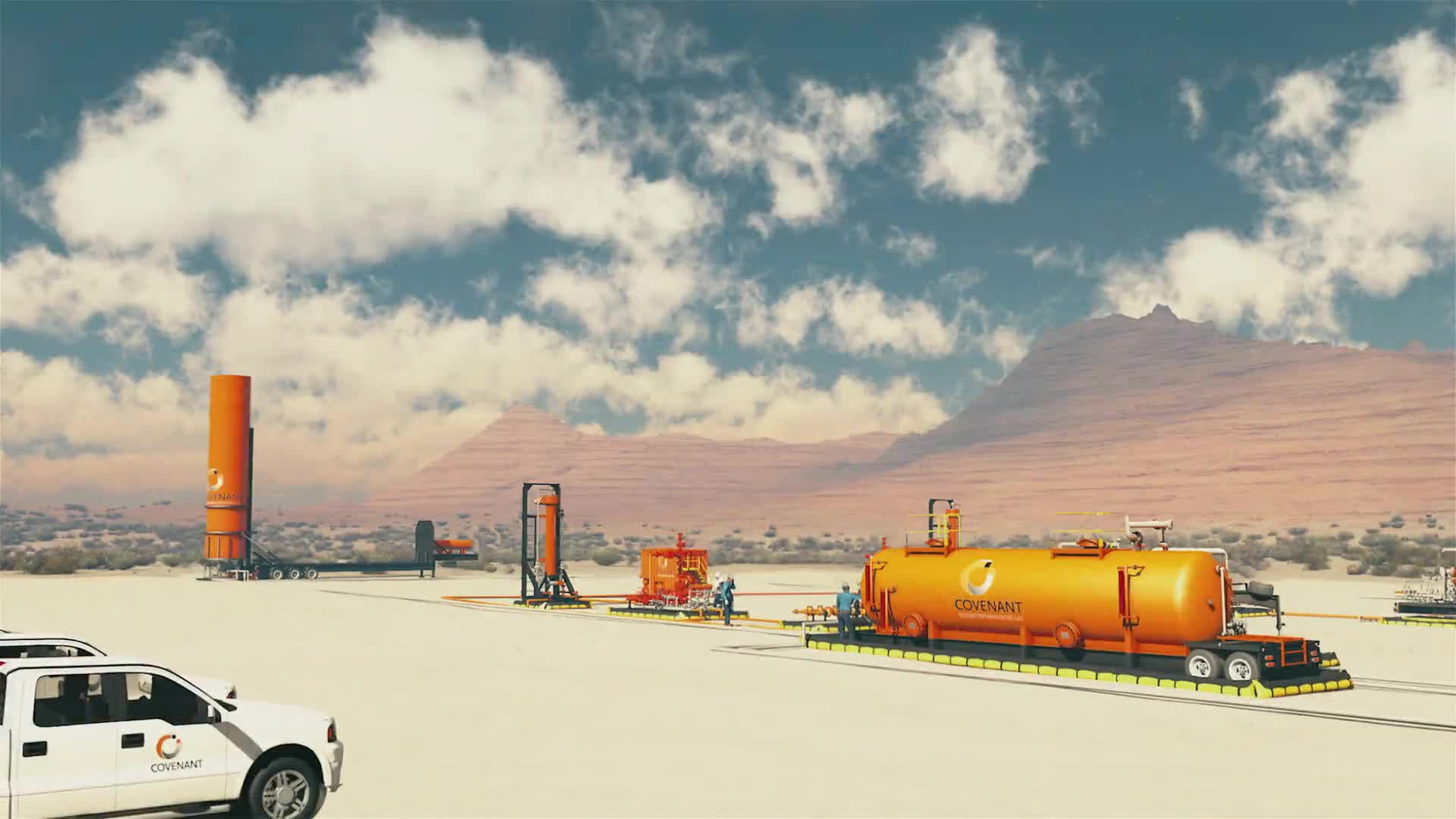
Frac Water Operations
Produced Water Disposal (with subsurface cutout)
Industrial Wastewater Processing
Onshore Pipeline Corridor
Low-Volume Offshore Water Treatment
High-Volume Offshore Water Treatment
Offshore Pipeline Segment
Extremely Unique Water Solutions Zone (featuring subsea and conceptual systems)
Each location required terrain integration, localized vegetation, custom fluid logic, accurate equipment animation, and camera-friendly compositions. Two high-stakes cutaways were required—one onshore (vertical injection below the surface) and one offshore (ocean floor split to reveal subsea manifolds, risers, and pipe routing).
The entire animation had to move smoothly—one continuous camera arc that floated, rose, dove, and curved through the terrain. That spline wouldn’t just define camera flow—it became the core logic for shot pacing, voiceover sync, and scene transitions.
Rapid Prototyping (RP)
We started by building the terrain in World Machine. It gave us the erosion control and flow modeling needed to carve out valleys, coastal edges, plateaus, and drainage zones that actually made geological sense. Erosion flow masks helped us place frac ponds and treatment sites where water would realistically pool—so from the first pass, the terrain followed logic.
That terrain mesh was exported to Vue for early lookdev. Vue gave us tools to experiment with atmosphere, sun direction, and procedural foliage across massive landscapes. It let us explore light behavior between inland desert and offshore haze. But Vue’s animation capacity hit a wall—it just couldn’t scale. So after pulling our stills and references, we moved the entire production pipeline into Cinema 4D.
C4D became the main platform for everything: animation, modeling, terrain assembly, and rendering. We chose the Physical Renderer over GPU options to keep full control of lighting consistency, reflection accuracy, and render predictability across layered passes—especially important for glass volumes, ocean surfaces, and atmospheric depth.
The master terrain was divided into eight zones, one per scene. Early on, we blocked out fluid systems using nulls and extrusion geometry—testing pipe flow, routing angles, and visibility from camera paths.
Asset Development & Scene Assembly
Various unique assets were built, optimized, or reworked for this piece. The client sent a few usable CAD models, but most had to be rebuilt from field photos or PDF schematics. Among the big builds:
Coiled tubing units with reel animation and fluid head
Frac tanks, manifolds, and flowback couplings
Vertical separators, sock filter skids, HiFlow racks
Nemoh systems with subsea intake/exhaust modeling
eelReel deep-sea fluid transport units
CrudeSep hydrocarbon recovery units for the FPSO deck
Low-poly support vehicles, trailers, gensets, cabins
Offshore vessels, riser arms, seafloor piping, and injection booms
Assets were grouped hierarchically—organized by function and location. That meant animation, camera reveals, and overlays could be staged with pinpoint accuracy in each zone.
The underground cutaways were modeled for believability. In the produced water zone, the terrain was opened to reveal earth strata, injection wells, and tunnel piping with animated connections. The ocean floor cutaway used Boolean carving and gradient textures to simulate deep marine geology, exposing pipe installs in a high-pressure environment. Both were prepped for particle effects and alpha masking for later post work.
Early Animation Planning
The animation backbone was a bezier spline. The continuous camera rig was controlled by null-based drivers that allowed full control over pan, tilt, and roll—tuned to match the voiceover and shot-by-shot intent. Each environment had its own “focus bubble”—a moment where the camera slowed, stabilized, and allowed the viewer to absorb what mattered.
We planned fluid logic early. Clean water used bluish-gray shaders. Contaminated fluids leaned green and brown. Pipes were built with spline extrusions and hose simulations to test routing visibility and camera angles.
Client Feedback Shaping Direction
Client and internal collaborations were detailed and frequent. We went through correction cycles on everything from flare stack color to trailer branding to the exact direction control panels faced. Specific asks included strict sequencing, from onshore to offshore and dirty to clean. Other requests were branded trailer visibility at the frac site, correct decal placement facing the camera, CrudeSep exclusive to the FPSO scene, color logic for clean vs. contaminated systems, and OSHA-aligned stair and panel orientation.
These notes shaped scene logic, timing, model details—even the story structure. Each RP revision targeted a specific correction round before moving to the next. By the time RP wrapped, the groundwork was solid. No guesswork. Every zone, every animation, every system transition was locked in context and tested in motion. Full Production wouldn’t be about building—it’d be about dialing it in.
Production (Full Production / FP)
Look Development
Full Production started by upgrading everything from Rapid Prototyping into fully detailed, production-grade geometry, materials, lighting, and water logic. This wasn't just a finishing pass—it was a structural buildout of eight distinct CETCO environments, each plotted precisely along a single continuous terrain, mapped to the camera spline and client schematic: Frac Water, Produced Water Disposal (with subsurface cutaway), Industrial Wastewater, Onshore Pipeline, Low Volume Offshore Treatment, High Volume Offshore Treatment, Offshore Pipeline (with subsea cutaway), and Extremely Unique Offshore Water Solutions. Each zone was positioned using both topographic logic and camera flow, allowing for localized control and isolation during production and rendering.
Materials were developed using C4D’s Standard/Physical Renderer, chosen for its reliable multi-pass outputs—object buffers, shadows, motion vectors, and depth—for post-processing. The overall aesthetic leaned hard into clarity and function: industrial roughness for metals, composites for tanks, and carefully tuned water shaders. We deployed five distinct water materials to differentiate clean, treated, and waste fluids—everything built for maximum legibility in daylight under a global Physical Sky lighting system.
Lighting was consistent across zones. A unified daylight rig ensured soft shadows and a stable tone from land to sea. Fill lighting was applied surgically—only where occlusion from trench walls or platforms made detail hard to read. Vegetation was instanced with slope-based density to provide environmental context without cluttering equipment visibility.
Asset Construction & Scene Integration
Each of the eight scenes was fully built out with various specialized systems modeled, textured, and positioned according to script logic:
Frac Water: Storage tanks, pump trailers, and manifold assemblies laid out across flattened zones for clean hose routing and camera visibility.
Produced Water Disposal: Cutaway terrain exposing layered strata, injection wells, and vertical pipe systems—geometrically correct and narratively aligned.
Industrial Wastewater: Custom refinery shells and separator gear arranged for horizontal visual rhythm.
Onshore Pipeline Corridor: Elevation changes, trench paths, flexible hoses, and surface-grade pipelines mapped to match terrain contours.
Low Volume Offshore Treatment: Small jack-up platform with lean deck gear, built for clarity and motion framing.
High Volume Offshore Treatment: Large FPSO rig with CrudeSep stacks, flare booms, and structured layout for top-down visibility.
Offshore Pipeline: Exposed trench showing risers and flange logic, optimized for top-down subsea visibility.
Unique Water Solutions: Nemoh and other subsea systems, placed in a minimal terrain basin for spotlight visibility.
CAD references were cleaned and retopologized to remove interior clutter. Where CAD wasn’t provided, assets were built from scratch using photos, schematics, and direct client documentation. Equipment was always grouped logically—intake here, treatment there, outflow downstream—aligned to flow logic and placed for maximum impact as the camera revealed each zone.
The two cutaways—one subsurface and one subsea—were Boolean-modeled and layered with gradient textures to reflect sediment depth and geological variance. These weren't generic slices—they showed stratified, field-relevant geometry designed to visually sell depth and infrastructure scale.
Technical Workflow & Render Strategy
The entire production lived in one Cinema 4D master file, broken into quadrant-based terrain chunks for viewport stability. Each zone lived on its own layer set, allowing fast toggling and isolated edits without blowing up the global file.
Shared materials ensured consistent behavior across similar surfaces—tanks looked the same whether in frac or offshore zones. Every major piece of equipment was tagged with a unique object buffer ID, making post-processing and compositing hyper-targeted and efficient.
Camera animation followed the same spline path established in RP. The only adjustments made were timing tweaks and easing curves to better sync with voiceover pacing. FOV stayed locked—no dolly tricks, no artificial zooms. The result: smooth, grounded movement through CETCO’s full water lifecycle.
Water shaders required refinement. Animated bump maps initially caused flicker, especially offshore. We resolved this by switching to world-based displacement and tuning Fresnel settings to reduce horizon-edge shimmer. In subsea zones, occlusion issues were corrected with point lights beneath the surface—just enough to illuminate the gear without breaking the daylight look above.
Choices & Reasoning
The visual strategy was built around one thing: technical truth. This piece wasn’t trying to entertain—it was built for engineers, operations teams, and technical stakeholders who need to see, understand, and believe what’s on screen. That meant a restrained, semi-photorealistic look. Clean edges. Logical layouts. No metaphors. No visual noise.
The choice to keep a continuous camera spline was strategic. CETCO’s water services are interconnected, and the animation had to reflect that. Chopping this into discrete shots would have undercut the narrative power and spatial logic. Instead, the camera traveled as their equipment does—fluidly, through onshore, offshore, and subsea conditions.
Modular zone builds kept complexity in check. Each environment was its own unit, built to slot into the broader terrain but flexible enough for quick edits or render swaps. That structure paid off at every stage—from revision cycles to render passes to final comp.
Every visual decision, from material finish to cutaway geometry, was made to reinforce CETCO’s credibility. The team didn’t decorate—every choice was about accuracy, clarity, and real-world plausibility. Labels were added only where they didn’t obscure equipment, and they were placed based on utility, not branding fluff.
In short: the animation worked the way CETCO’s systems do—clear, connected, and engineered to perform.
Post-Production & Delivery
Final Compositing & Color Grading
Compositing was handled in After Effects using object buffers, Z-depth, and shadow passes from Cinema 4D’s Physical Renderer. We layered these elements to build accurate depth cues, sharpen equipment silhouettes, and control scene lighting. Curves and selective color adjustments kept the look consistent while clearly differentiating water types—produced, treated discharge, and frac water—across the sequence.
Each scene’s shadow contrast was fine-tuned, with haze overlays added in offshore zones to strengthen atmospheric depth. Pipeline and subsea sections received subtle glow passes to remain visible against darker terrain. Everything stayed within CETCO’s color standards—equipment, logos, and fluid hues untouched beyond approved parameters.
Labeling & Brand Consistency
Each environment was using 3D-tracked nulls from the layout stage. Lower thirds identified the eight core zones—and nothing more. Labels appeared and disappeared with smooth timing matched to camera flow, using CETCO’s brand typography. These overlays serve clarity, not decoration.
Late tweaks included updated label terminology, refined camera pause timing to match voiceover delivery, and final alignment checks with narration. Every edit preserved CETCO’s technical tone—no flashy colors, no gimmicks, just precision.
Composite drafts were reviewed in full with voiceover, then approved by the client. Minor timing tweaks were made in After Effects using buffer isolation—no need for 3D re-renders. That flexibility kept delivery agile and accurate.
Delivery
The final video shipped as a single, continuous 1080p H.264 master—optimized for sales decks, presentations, and events. It’s self-contained, self-explanatory, and voiceover-ready.
We also exported still frames from key camera moments in each of the eight zones—ideal for marketing visuals, technical documentation, or proposal materials.
Transcript:
CETCO Energy Services, has been serving the Oil & Gas Industry for over 25 years.
We treat high volumes of produced water in a small footprint, either on a temporary or permanent basis for compliant overboard discharge. Our specialty is solving problematic water challenges, anywhere including, at subsea levels.
Nemoh, our Subsea Fluid Collection & Processing System is our proprietary technology that captures limited quantities of trapped hydrocarbons and processes water-based fluids for subsea discharge.
We provide pipeline and flow line solutions such as the removal of toxic chemicals and hydrocarbons from hydro test and hydrate remediation fluids, and the removal of paraffin and asphaltene blockages at distances greater than operating standard practices.
CETCO has the talent and years’ experience to design, operate, and troubleshoot systems to treat stored slop water and produced water on a temporary or permanent basis. We help our customers improve efficiencies that otherwise prohibit them from meeting environmental requirements.
We provide extremely unique services. We remove arsenic, zinc, and mercury from produced water for compliant discharge and remove hydrocarbons from glycol-based fluids to enable recycling.
Onshore, we provide an array of services, including the treatment of water, oil, and gas.
And the treatment of many different segments of Industrial wastewater from many different industrial segments.
Clean water is a precious resource and utilized for hydraulic fracturing. CETCO provides water transfer and fluid treatment options to re-claim and re-use water using our mobile onshore electrocoagulation system.
CETCO isolates and treats completion and acid stimulation flow back fluids from new and recompleted offshore wells to minimize facility process disruptions, facilitate compliant discharge, and reduce waste disposal.
In aged and undersized production facilities, we separate and recover valuable hydrocarbons and remove contaminants from produced water for injection or re-use.
Our wide range of water solutions, onshore and offshore, has established CETCO Energy Services as The Global Environmental Service Leader in problematic water solutions for the Energy Industry.